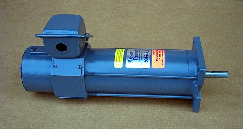
Strippit Machine Servo-Drive Motors
The Strippit Company used D.C. Brush-Type Servo Motors on all their HECC80 CNC and "A" NC Control Turret Punch Machines Manufactured in the 1970's & 1980's.
This discussion will pertain Specifically to Servo Motors that were used on
Strippit Machines of this Era. They are Typically Tagged as
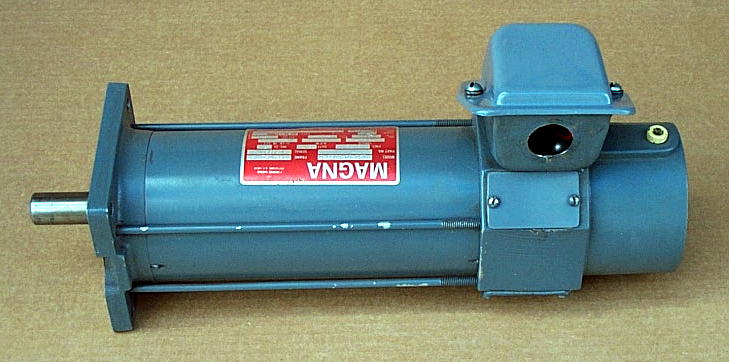
Porter / Peerless / Porter Peerless / General Electric / Magna / or
Machine Technologies on the Motor Name-Plate.
I Stock, Here at Machine Technologies, All these Servo Motors, and I Can Provide
Motor Testing, Rebuilt-Exchange Motors, Rebuilding of Your Motors, & Repair Parts.
Later-on, in 1986 on FC1000/3's, and in 1987 on the FC1250/30/1500 Machines,
Strippit started Converting from HECC80 Controls to Fanuc GN6 CNC Controls,
which used Fanuc's Own D.C. Servo Drives & Servo Motors.
Around 1989, Strippit Converted again to New Fanuc OP Controls, which used a
Newer & Superior Motor Technology, A.C. Servo Drives & A.C. Motors.
A.C Servo-Motors & A.C. Motor-Drives are Superior Technologies,
But God Help You if you Need to Replace one of these Fanuc Motors,
because Fanuc often Quotes Months Delivery and Costs of $10,000 to $25,000!
I Do Not Repair or Stock Any Fanuc Motors at this Time.
Following are DC Servo Motor Types, and the Strippit HECC80 Control Turret Punch Machines that they were Used On. Some Motors were Also used on Other Machines.
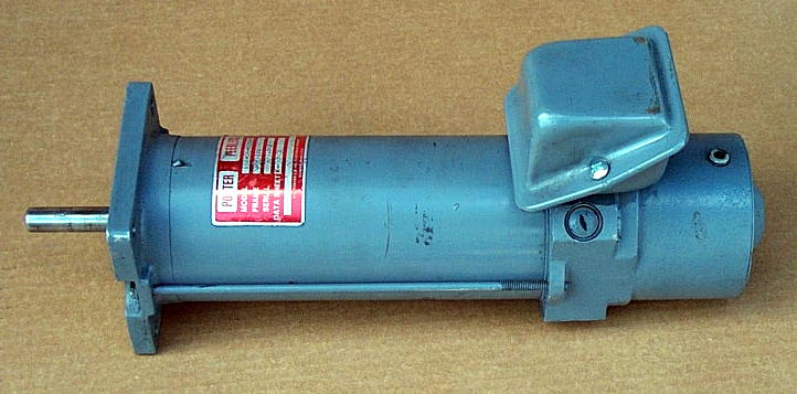
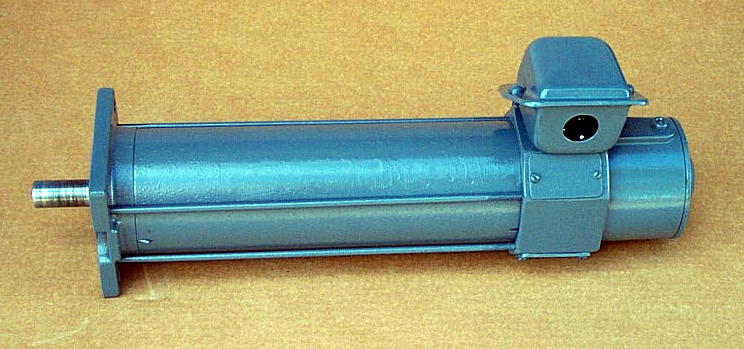
Strippit #17539-000
Model #181-04-0020-0
Used on T-Axis of FC1000/1, FC1000/2,
and FC1250/30/1500 Machines with
20-Station Turrets. But is Not used on
33-Station FC1250/30/1500 Machines.
This Motor is the Same as #17497-000 Motor, Except it does Not have Air Cooling Ports. You can Substitute a
#17497-000 for a #17539-000 on a
T-Axis, but you can Not Substitute a #17539-000 for a #17497-000 on a X-Axis
because of the Lack of Cooling Ports.
Brushes & Caps are Same as #17497-000.
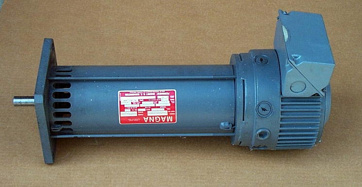
Strippit #17497-000
Model #181-04-0011-0
Used on X-Axis on Strippit FC750, FC750/2, FC1000/1, FC1000/2
Machines. Has a 1 1/2" Pipe-Thread Cooling-Air Inlet Port at the Back of Motor, Air goes through Motor and Out Slots at Bottom Front of Motor.
Uses 4 -- #17506-000 Brushes.
Most Motors use 3/4" Small-Disk
Out-Side Thread Type Brush Caps,
But, Older Motor Versions use
Cup-Type Brush Cap with
Inside Threads.
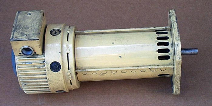
Strippit #17360-000
Model #181-12-0015-0
Used on Y-Axis of FC750, FC750/2,
FC1000/1, FC1000/2, FC1250/30/1500,
FC1250/30/1500 LaserTool, FC1250/45, LaserCenter, FC51/30, FC51/40,
and Blanking Center Machines.
Motors use 6 -- #17788-000 Brushes and 7/8" Disk Brush-Caps.
Strippit #17538-000
Model #181-12-0019-0
Used on X-Axis of FC1250/30/1500,
FC1250/30/1500 LaserTool, LaserCenter, FC1250/45, Old Style FC1250/30, FC51/30, FC51/40 and
Blanking Center Machines.
This is just a Shorter Version of the #17360-000 Motor.
Motors use 6 -- #17788-000 Brushes and 7/8" Disk Brush-Caps.
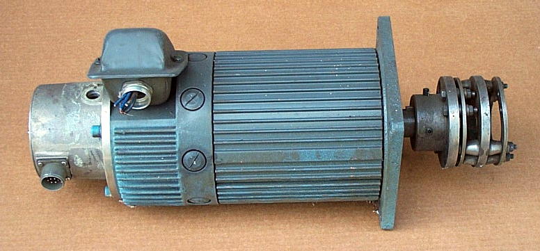
Strippit #17510-000
Model #183-18-0190-0
Used on the T-Axis of FC1250/45,
Old-Style FC51/30, FC51/40, and
FC1250/30 (NOT FC1250/30/1500) Machines.
Motors use 8 -- #17506-000 Brushes and Special Top-Hat Disk or the
Small 3/4" Disk Brush-Caps.
This particular Motor is a "Pull" from a Machine I Scraped, and still has it's Coupling & Special Geared Resolver Feedback Package attached.
Strippit #19463-000
Model #181-04-0034-0
Used on T-Axis of FC1000/3 and FC1250/30/1500 Machines with
33-Station Turrets.
Motors use 4 -- #19463-000
"Type-C" Brushes, and have a
Steel Rectangle Brush-Cover.
Motor was also Sometimes used on
X-Axis of FC750 & FC750/2 and
X & T Axis of FC1000/1 & FC1000/2
Machines in a Mistaken Attempt at Increased Reliability. They Work OK there, but give Little Added Benefit.
I now also use this Motor as a Substitution for the #17497-000 and #17539-000 so that I only have to Stock 1 Motor instead of 3. This particular Motor is one that I Personally Rebuilt.
Strippit #19399-000
Model #191-04-0029-0
Used on Y-Axis of FC1000/3 Machines.
However, with a Bit of Grinding for Mechanical Clearances, it can be used as X-Axis Motor on FC1500/45 Machines.
Motors use 4 -- #19463-000 "Type-C" Brushes with
Steel Rectangle Brush-Covers.
Strippit #19462-000
Model #191-04-0033-0
Used Only-On the
X-Axis of FC1000/3 Machines.
Motors use 4 -- #19463-000 "Type-C" Brushes, and have a
Steel Rectangle Brush-Cover.
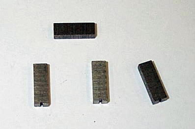
#17506-000 "Small Brush"
.250" Thick x .500" Wide x .625" Long
The Round Plastic Brush Caps used on these Motors are Easily Chipped and Broken by
Careless Removal with a Screwdriver !!! Make a Removal Tool from Thin Sheetmetal
Cut to the Width of each Caps Slot. We Stock the Following Replacement Brush Caps.
Motor Brushes & Caps
Motor Brushes should be Checked Regularly for Wear! Replace Brushes if Worn to Half their New Length. Check X & T Motor Brushes once a Year, and check Y-Axis Brushes every 6-Months. Check more often if these seem to be Wearing Rapidly.
I usually "Tag" Each Motor on Machine with It's Brush "Inspection Date",
or else keep a Repair Maintenance Log Book with this Data Recorded in it.
If you Don't Check them, Brushes will Wear Down until Carbon is Gone, Then the
Copper Wire & Steel-Spring Digs & Burns into the Commutator, Ruining Motor.
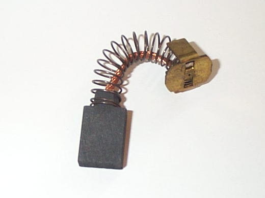
#17788-000 "Large Brush"
.250" Thick x .750" Wide x .750" Long
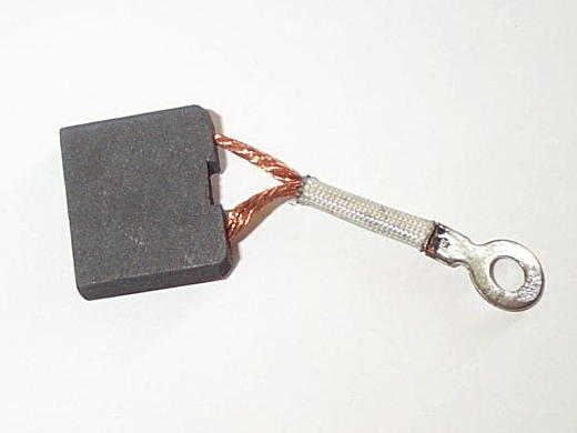
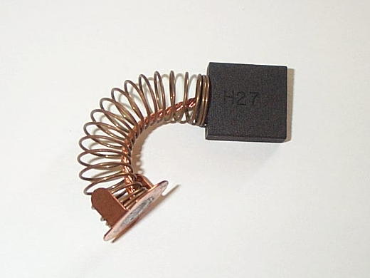
#19463-000
"Type-C Brush" for FC1000/3 & FC1500/45 Machines
.250" Thick x 1.000" Wide
x .875" Long
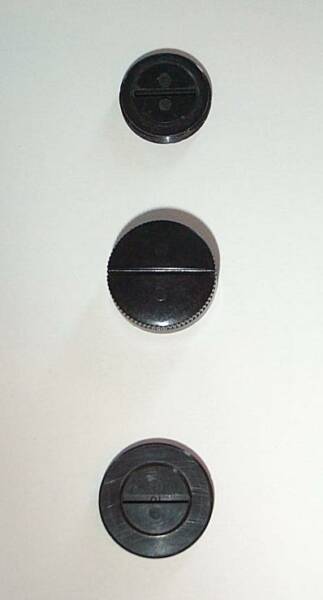
"Small-Disk" Type Brush-Cap that are
used on Most Motors that use the
Small #17506-000 Brush.
3/4" Wide with Outer-Diameter Threads
"Small-Cup" Type Brush-Caps that are
used on Old-Style Motors that use the
Small #17506-000 Brush.
13/16" Wide with Inner-Diameter Threads
"Large-Disk" Type Brush-Caps that are
used on Most Motors that use the
Large #17788-000 Brush.
7/8" Wide with Outer-Diameter Threads
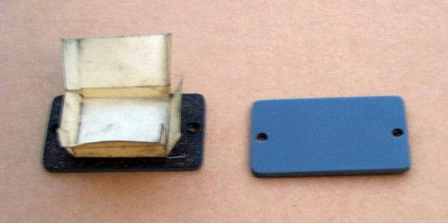
Steel Rectangle Type Brush-Cover that
are used on FC1000/3 "Type C" Motors that use the #19463-000 Brush.
Early Version Covers had Cork-Insulation Glued on the Underside. Later Covers Also had a a Heavy-Paper Shield to help Protect against the Brush-Wire from Shorting against Motor Housing.
This page was last updated: June 26, 2025

(DC Generator) that tells Servo-Drive how Fast
the Motor is Rotating. A Properly Working Tach is Critical to Operation of Servo-Drive!
A Good Clean Tach Assembly, on Strippit Servo Motors, will read About 60 to 75 Ohms. Check it,
Rotate Motor Shaft a Bit by Hand, and Check it again. Repeat several times more to gain confidence that
Tach is Working OK in All Positions.
A Bad Tach will show Thousands or More of Resistance in Ohms. Usually caused by;
--- Dirty or Tarnished Tach Commutator, Clean with
Soft Pencil Eraser or Fine Scotch-Brite Pad.
--- Stuck Tach Brush. Take out Holder & Clean out
with Electrical Cleaner, and Very Lightly Sand
4 Brush Sides with 400 or 600 Grit Paper.
--- Bad Tach Armature. The Potting Compound on
Armature Shrinks with Age & Breaks Wires in
Tach Armature and then Must be Replaced!
--- Bent Tach Brush Spring. You can NOT Fix Bent
Springs! Spring or Tach Ring Must be Replaced!
Springs are Bent by Careless Brush Insertion!
I Carefully Pull-Back the Side-Of-Spring with a
Small Screwdriver while Pushing In Tach Brush
with Another Small Screwdriver, then Insert a
Piece of Paper Clip in Hole to Hold Brush in.
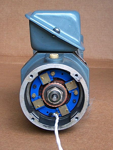
This Tach-Ring is Installed Upside Down!
Tach-Cable is Usually at the
Top of Motor.
This Motor has the Original "Blue" Type Tach-Ring
with
Original Type 25-Segment
Tach-Armature.
Tachometers
In the Good-Old Days,
there was just 1 Type of Tach-Ring & it's Armature, the "Blue" Type.
Then, there was a 2nd Type, the "Black" Type-Ring & it's "Black" Type Armature.
The "Black" Type Used a Different Size Tach-Ring, Armature, and Magnet-Set
Inside Motor, so None of the Parts are Interchangeable with the "Blue" Type!
However, as Technology Changed and Venders Come & Go, The "Color" of
Tach-Ring and Tach-Armature has become Almost Meaningless.
I have seen Blue, 2 Sizes of Black, Green, Tan, Red, Etc., of Tach-Rings!
There are really still only 2 Types regardless of the Actual Color.
I Measure Outside Diameter of the Tach Armature to tell them apart.
The "Blue" Type of Tachometer Assemblies will have a Tach Armature
with a Outside Diameter of about 1.895 Inches.
The "Black" Type of Tachometer Assembly will have a Tach Armature
with a Outside Diameter of about 1.937 Inches.
To further complicate, "Blue" Tach Armatures Originally had 25-Segments & Windings.
But, to get Better Servo Response at Low Speeds for Laser Continuous Contouring,
a New Type of Armature was Manufactured with 33-Segments and Windings.
As long as they are of the Same Type (Blue or Black) and Same Size, 25 & 33 Segment Types are Interchangeable, but with 33 Type giving Better Servo Response.
Both "Blue" & "Black" Tach Rings used Same #17774-300 Tach-Brushes.
Old Brushes were a Dark-Black Color
as they were made of a
Dry Hard Carbon that sometimes would Wear a Groove into Tach Armature,
which would Destroy it.
Later Brushes had More Graphite in
Carbon-Mix, which provided some Lubrication Properties, and would Prevent the Wear-Problem as
Machines got Faster & Faster.
These Newer Brushes were
Silvery in Color and had a Waxy Feel.
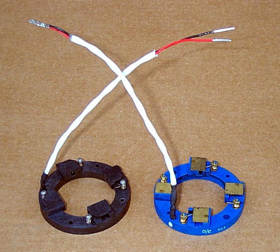
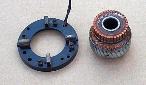
There are at Least 2
"Blue" Types of
Tach Brush Holder Rings,
Part #17774-100
The Original Blue-Color
"Blue" Type
And
a Late Manufacture
"Blue" Type that
happens to be
Black in Color!
These are Both
"Blue" Rings in Photo!
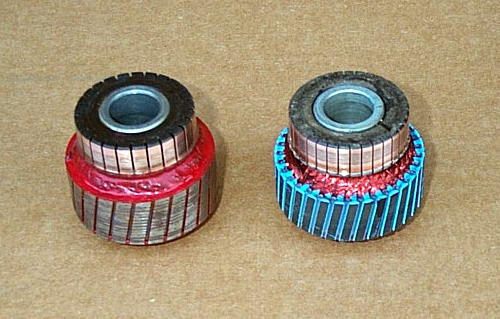
Original "Blue" Type 25
Segment Tach Armature that
happens to be Red, #17774-000
On Left, Original "Blue" Color
Tach really referred Only
to Tach Ring-Color,
NOT the Armature Color.
On Right, a Late Manufacture
33-Segment "Blue" Type Armature used in Later Motors.
Here is the Real
"Black" Tach Ring #17774-500.
And, it's #17774-400 "Black" Type Armature.
I Believe that all
"Black" Tachs used only this Type 33-Segment Armature,
which is Different from the "Blue" 33-Segment Armature.
Note! Most Motors used the "Blue" Tach. I Believe The "Black" Tach was only used
on some Later #17360-000
and #17538-000 Motors.
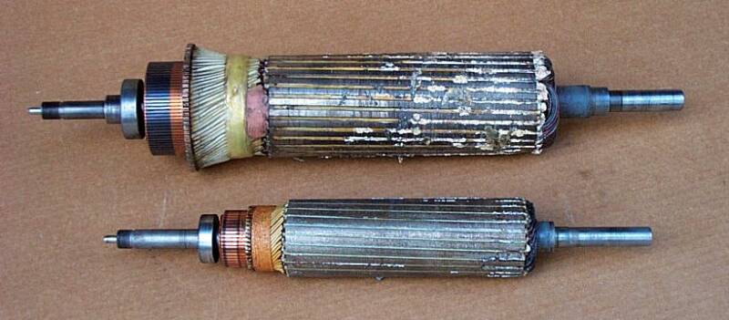
Motor Killers
Above are 2 Armatures from Stalled Servo Motors that got So Hot that
Plastic Insulation Melted and Oozed Out of the Armatures!
This Starts to Happens at about 400 Degrees Fahrenheit! The Magnet-Wire Insulation Breaks-Down, Windings Short & Arc Together, and Motor becomes Junk.
Here are Some (But Certainly Not All) of the Causes of Servo Motor Failure;
1 --- The Biggest Cause of Servo Motor Failure is Heat.
When a Motor is Stalled, it Pulls Maximum Current,
which can Overheat and Burn-Out a Motor in only a Minute or Two,
if Operator is Not Smart Enough to Quickly Shut-Off Machine and Clear the Jam-Up!
--- Some causes are a Jammed X or Y Axis. This Occurs when Machine Pulls a Slug
Jamming Part-Sheet, or a Punch Sticks-Down causing a Jam With a Short
(Under 3 Inches) Axis Move so the Control does NOT Declare a "Excess Error" which would Shutdown Servo Drive. So, Control keeps Powering Stalled-Jammed Motor
to Move. If Operator does Not Quickly shut off Machine, you Risk Burning the Motor.
--- Sometimes X or Y Axis Limit Switches are Not Working, or some Knuckle-Head "Adjusted" Switches to try to get a Little More Travel Length on Axis. Then, if you
have a Operator Error, or Programming Error, or Control Failure that causes Axis to
Hit the End of Axis-Travel, you Stall the Motor like Above, and Burn Out Motor.
--- Similar Motor-Killing Jams on Turret from;
--- Pulled-Slugs Jamming Turret to Part-Sheet,
--- Too-Tall Tool Hitting Ram,
--- Jammed Part-Sheet still Stuck to a Tool,
--- Slugs in Gears,
--- Slug Jammed between Lower Turret & Anvil Underneath
When a Jammed Turret tries to make a <3" Short 1-Station Move, there will be
No Excess Error Condition to Stop Control from Driving the Servo Motor.
Jammed Turret causes same Stalled Motor Burn Out Problem as Motor Overheats in a Couple of Minutes while Operator is Still Scratching His Head on What's Wrong......
Also, FC1000/1 & FC1000/2 & FC1250/30/1500 Machines with 20-Station Turrets
Rarely Burned-Out T-Motors because Strippit used a Small 8.67 Heater in the
T-Servo Overload-Relay to Protect Motor. When Jammed, Heater would
Quickly Heat-Up & Trip-Out similar to a Circuit-Breaker and Saving the Motor.
But, when Strippit changed to 33-Station Turrets, they Changed Heater Size to a
Large 21.4 Heater that would Never trip-out before Motor Melted! I sometimes
change 21.4 Heater Down to about a 10.0 to 13.00 Size to help prevent this problem.
FC1000/3 Machines with G.E. Model 3 Servo used a Electronic Overload instead of
the Heater & Overload-Relay as it was Cheaper for G.E. when building Servo Drives.
But, Electronic Overloads NEVER Trip to Save the Motor on these Machines!
I sometime Retrofit the old Heater & Overload-Relay on to these Machines, in the Field.
Last Project I Did before Leaving Strippit was Designing Overload-Relay Retrofit
which Strippit Added to Production FC1000/3 Machines Starting at Serial Number 200.
These Same Technicians Then think a Megohmmeter is The-Answer,
and will tell them a "Bad" Motor.
In Most cases, this is Also Wrong!
A Ohmmeter puts out about a Volt or 2, and then Measures Current Flow,
to Determine the Resistance of a Circuit.
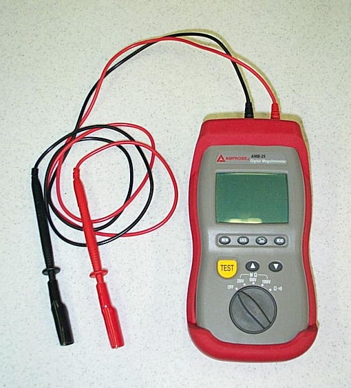
A Megohmmeter uses a Hi-Voltage to do the Same thing. My Megohmmeter at
Left can Put-Out Over a Thousand Volts!
The Idea is, at Hi-Voltage, Weak, Bad,
or "Cooked" Insulation will Break-Down
and the Megohmmeter will Detect it.
But, You usually can Not Read Insulation
Breakdown, Winding to Winding, with
Either Type of Meter! Both Melted &
Shorted Armatures in Picture Above will
Pass Megohmmeter Test at the Highest
1000 Volt Setting, yet are Quite Bad!
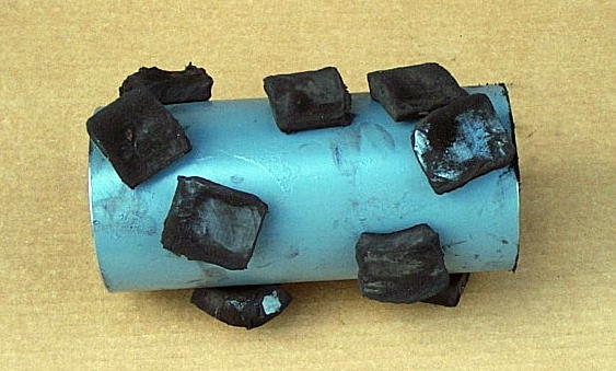
The Magnet Shell
at Right Got So Hot
that Glue that Holds Magnets inside
Broke Down, and all
Magnet-Segments came out when Motor
was Disassembled.
It's Junk Now Also.
Some Technicians try to Determine a Shorted or Burned-Out Motor with a Ohmmeter.
You Can't!!!
Most Motors Burn-Out by Shorting their Windings Together,
and You Can Not Ohm-Out This Problem!!!
These Technicians Also Meg the Armature to Ground.
As there is Always Dirt and Carbon Dust Coating Inside of Motor,
they Will Always get a "Reading".
They then Declare Motor is "Shorted", and send it out to be Rebuilt.
The Motor Could Indeed be Bad,
But This Test will NOT Prove it One Way or the Other,
as this is NOT the Normal Failure Mode!
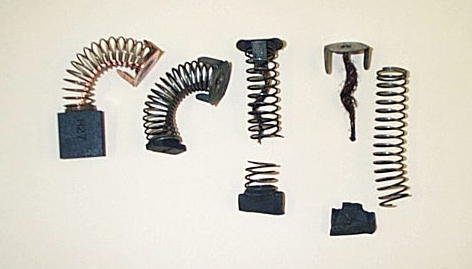
3 --- Another Common Cause of Motor Failures is Worn-Out Brushes.
Customers Fail to do Routine Maintenance like Checking their 3 (X, Y, T) Servo Motor Brushes, which then Wear-Down Until they Destroy the Motor Commutator,
and possibly also the Servo Drive Electronics.
I can Sell You New Brushes or I can Sell You Motors & Servo-Drives. Your Choice.
Below Photo Shows a New Brush on the Left, and 3 Worn-Out & Broken Brushes
I Dug-Out of a Customer's Motor. They got to Buy a New Motor.
4 --- Another Common Cause of Motor Failures is Impact Damage.
Motors are Relatively Fragile. Impacts can Break the Magnets Loose inside Motor,
Pull Out the Studs Holding Motor Together, and Break Resolver Feedback Package Off the End of Motor, among other Failures. People in Shops Run Into Motors with their Fork-Lifts and Bump them with Work-Tables. Put Guard-Rails around Machine!
Replacement Motors and Motors being Returned for Credit are Often Damaged by Shipping! They Must be Very Well Packed in a Heavy-Duty Carton with Lots of Tight Packing Materials. I Now Double-Pack the Bigger Motors inside 2 Boxes!
I often get a Return Motor Back that was just Thrown into a Box with Little or No
Packing Material around it, and it comes-in with Part of Motor Sticking Outside of Box!
Needless to say, These Damaged Motors Do NOT Receive Any Credit for the Return.
2 --- More Motor Heat Failures are caused by No Cooling Air-Flow.
The X & Y Motors, and the T Motor on some Machines, are Forced Air Cooled.
-- Is there a Strong Air-Flow coming out of Motor?
-- Is the Cooling Fan Motor Running?
-- Is the Air Filter Clogged-Up?
-- Are the Air Hoses Rotted out?
Find and Repair the Above Problems!!!
5 --- Local Motor Shops Permanently Kill a Lot of Servo Motors.
When a Shop Burns-Out a Servo Motor on one of their Machines,
they usually try to go Cheap, and "Give the Local Motor Rewind Shop" a Try.
The Problem Is, Most Motor Shops are Set-Up to Rewind Only A.C. Motors,
NOT D.C. Servo Motors, which are Very Different!!!
These Motor Shops Always Do 1 of 2 Things;
A --- They Take Apart Motor and Damage Armature & Tach-Armature & Magnet Shell Further. They then "Cut" Commutator, usually Improperly, which Ruins this Critical Part. Finally, they replace Bearings, Cut-Down and Adapt some Brushes to Fit,
Paint It, and Declare it "Rebuilt". When Customer gets it Back,
it is Still Bad or even Worse than Before. Then Customer (You) is Pissed as you now have a "Rebuild" Bill and your Machine is Still Not Running, and
You & Repairman Still Don't Know What's Wrong.
B --- Or, They usually Damage Magnet-Shell, Armature, and Fragile Tachometer Armature because they do Not Know how to take Motor Apart. They then Screw-Around with Motor a While, then they Give-Up, Throw All Parts Loose & Damaged in a Box, and return the Whole Mess to Customer. Then Customer sends it to Me for a "Trade-In", as
I Sell Most Motors on an Exchange Basis. I have been Repairing Strippit's for Over 35 Years and I have seen "A" & "B" above, Over & Over Again!
If Anyone has Opened-Up Motor & Tried to "Repair It", I No Longer Give Any Credit!
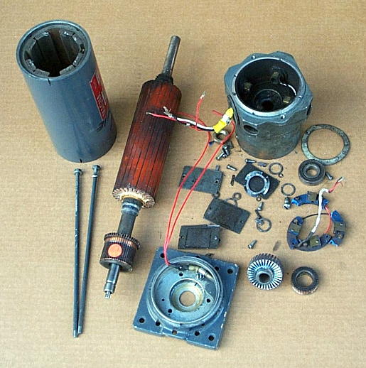
Below, is a Photo of 1 such Servo Motor, Just as I Received It from a Customer,
who used a "Local" Motor Shop to "Try to Rebuild".
--- Motor Arrived with Shaft Sticking Out of Box.
--- All Parts were Loose Inside Box.
--- Tach Ring is Broken in to Pieces.
--- Wire was Stripped-Off Motor Armature & Commutator, Damaging Both.
--- Tach Armature had it's Wire Stripped-Off, and is Broken into 2 pieces,
--- Many Parts are Missing.
So, For those of You who are a Little Slow on the Up-Take Here,
Do NOT Take Your Servo Motor Apart,
You Will Damage It !!!
Do NOT Take Your Servo Motor To The "Local" Motor Shop,
They Will Damage It Even More!!!
Because of this Problem, I started Rebuilding Servo Motors for Strippit Machines 35+ Years ago. All My Servo Motors are Washed, Armatures are Completely Rewound, Magnet Shells Replaced if Necessary, Brush Holder Problems Repaired, Tach Ring
and Tach Armatures Repaired, New Brushes Installed, New Bearings Installed, and any other Problems Repaired.
And Finally,
Every One of My Servo Motors are Run on One of My Strippit CNC Punch Machines,
and Tested for Proper Operation, Tuning, and Accel & Decel Characteristics.
No one Else in the World Does This, Servo Motor Testing on a Real Strippit Machine,
so We & You Know that it is a Good Motor that will Perform to Spec on Your Machine.
Motor is then Painted & Boxed-Up after this Final Machine Testing,
so we can Just Pull-It off the Shelf for Quick Overnight Shipping.
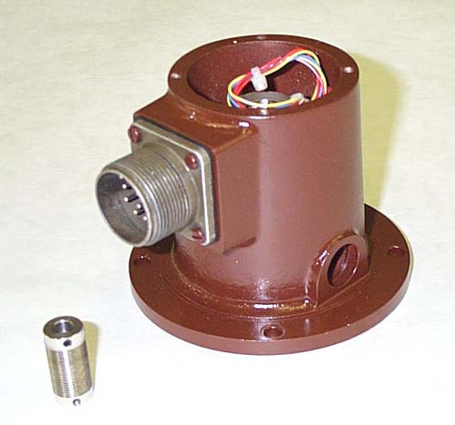
6 --- Resolver Feedback Packages and Couplings Eventually Wear-Out and Fail.
Cables going to the Feedback Package can also Fail.
This Loss of Position Feedback can Then cause Axis to Run-Away and Crash into the End of Axis Travel, which can cause both Mechanical Damage and Heat Damage
to Motor from being in a "Stalled" Condition.
If you see occasional Axis "Jumping Position" this can be a Warning Sign
that Resolver Feedback Package or Cables are Wearing out.
Fix or Replace Now to Prevent More Problems!
#17546-000
Resolver Feedback Package
and
#17648-000
Resolver Coupling
We Keep Both
of these
Parts In-Stock.
To Recap, We Stock Strippit;
--- D.C. Servo Motors
--- Do Servo Motor Testing & Rebuilding
--- Motor Brushes
--- Brush Caps
--- Tachometer Armatures
--- Tachometer Rings
--- Tachometer Brushes
--- Resolver Feedback Packages
--- Feedback Cables
--- Resolver Coupling
--- Servo Motor Electronic Drives
--- Servo Drive Electronic Repair Parts
--- Servo Drive Electronic Testing

There is Much More
Servo-Drive & Servo-Motor Information on Our
Web-Pages, Go There!


Above is a Servo Motor, as I received it,
after a "Local Shop" tried to Rebuilt it.
It's All Junk now, So Customer Got to Buy a New Motor from me.